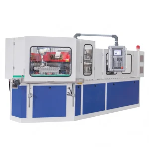
Máquina automática de moldeo por inyección-soplado de un solo paso EP40 400KN para botellas farmacéuticas y cosméticas CE ISO
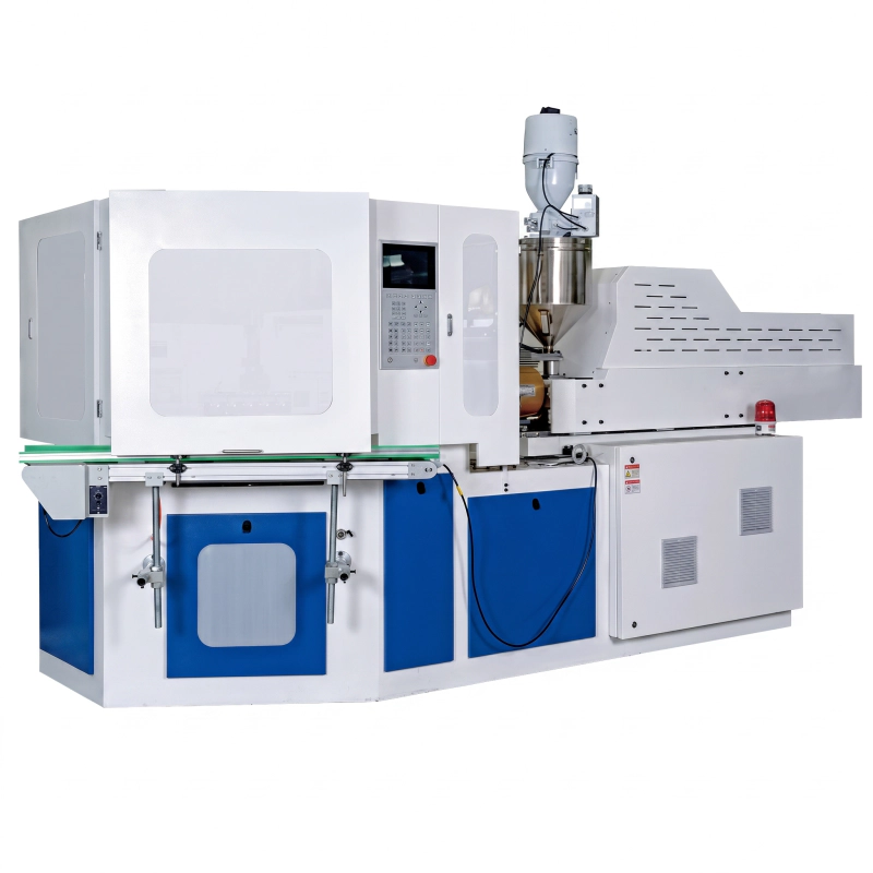
La máquina de moldeo por inyección-soplado EVER POWER EP40 ofrece una fuerza de cierre de 400 kN, un peso de inyección de 190-260 g, un ciclo de secado de 3,5 s y una producción de hasta 9 cavidades. Proceso IBM de tres estaciones y un paso para la fabricación de botellas sin rebabas para productos farmacéuticos, cosméticos y químicos de uso diario, desde 1 ml hasta 1500 ml. Certificación CE, accionamiento servohidráulico, ahorro energético de 201 TP3 T en comparación con el promedio de la industria.
¿Qué es la máquina de moldeo por inyección-soplado de un solo paso EVER POWER EP40?
La EVER POWER EP40 es una máquina IBM (moldeo por inyección-soplado) totalmente automática de un solo paso, diseñada para la producción de contenedores huecos de precisión. Como máquina dedicada fabricante de máquinas de moldeo por inyección-sopladoEVER POWER ha concentrado décadas de experiencia en herramientas y procesos en este modelo, ofreciendo una máquina donde la botella completa, desde la inyección de la preforma hasta el soplado final y la eyección, se completa en un solo ciclo de máquina sin intervención del operador, sin transferencia de material entre máquinas y sin las rebabas y los residuos de la línea de separación que caracterizan a los sistemas de soplado por extrusión.
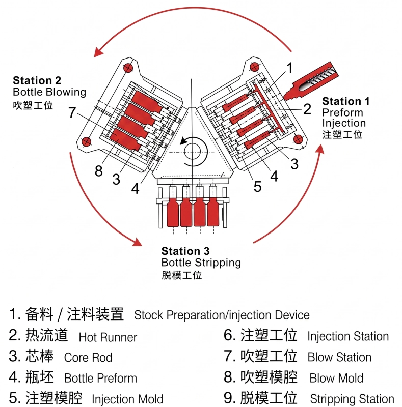
Este una máquina IBM de un paso Es la opción preferida para el soplado de botellas farmacéuticas y la fabricación de envases cosméticos, donde la consistencia dimensional es fundamental. Cada ciclo de la EP40 ejecuta tres operaciones simultáneas: mientras se inyectan nuevas preformas en la Estación 1, el lote anterior se sopla para darle su forma final en la Estación 2, y las botellas terminadas de la Estación 2 se desmoldan y se transportan a la cinta transportadora de salida en la Estación 3. Este paralelismo triaxial significa que la producción es igual al tiempo del ciclo de inyección únicamente, no a la suma de inyección, soplado y eyección, lo que le otorga a la EP40 una ventaja significativa en el rendimiento sobre los sistemas de soplado y estirado de dos etapas para envases de volumen pequeño y mediano.
Proceso de tres estaciones: Cómo funciona el EP40
Estación 1 - Inyección de preformas
Los gránulos de plástico se funden en el cilindro y se inyectan en la cavidad de inyección bajo presión controlada. El cuello de la botella y la geometría de la rosca se forman con precisión en el molde de inyección. El molde se abre y el mandril que contiene la preforma caliente se transfiere a la Estación 2 mediante la torreta giratoria.
Estación 2 - Moldeo por soplado
La preforma caliente se infla con aire comprimido procedente del núcleo del mandril. La forma de la botella viene determinada por completo por la cavidad del molde de soplado. El aire infla la preforma hacia afuera contra las paredes enfriadas del molde, y la botella adquiere sus dimensiones finales. El molde se abre y la torreta avanza hasta la Estación 3.
Estación 3 - Expulsión y transporte
Las botellas terminadas y enfriadas se retiran de los mandriles y se descargan en la cinta transportadora de salida. Dado que las tres estaciones operan simultáneamente, el ciclo se repite continuamente. No se requiere ninguna operación secundaria, prensa de desbarbado ni recalentamiento de las botellas; las tres operaciones comparten un único ciclo de reloj.
Parámetros técnicos principales - EVER POWER EP40
| Parámetro | Artículo (EN) | Unidad | EP40 |
|---|---|---|---|
| Sistema de inyección | |||
| Diámetro del tornillo | Diámetro del tornillo | mm | 40/45 mm |
| Relación L/D del tornillo | Tornillo L/D | - | 22:1 |
| Peso de inyección | Peso de inyección | gramo | 190/260 g |
| Potencia de calentamiento | Potencia de calentamiento | KW | 7,5 kW |
| Zonas de calentamiento del barril | Número de zonas de barril | - | 3+N |
| Accidente cerebrovascular por inyección | Accidente cerebrovascular por inyección | mm | 120 mm |
| Sistema de sujeción | |||
| Fuerza de sujeción de inyección | Fuerza de sujeción de la inyección | KN | 400 |
| Carrera de apertura de la inyección | Carrera de apertura para la inyección | mm | 165 mm |
| Fuerza de sujeción por golpe | Fuerza de sujeción del soplado | KN | 60 |
| Golpe de apertura | Golpe de apertura para soplar | mm | 140 mm |
| Altura del elevador de torre | Altura de elevación de la mesa giratoria | mm | 70 mm |
| Moho | |||
| Tamaño máximo de la platina (largo x ancho) | Tamaño máximo de la platina (largo x ancho) | mm | 480x340 mm |
| Grosor del molde | Grosor del molde | mm | 180 mm |
| Diámetro máximo de la botella | Diámetro de la botella | mm | 120 mm |
| Altura máxima de la botella | Altura de la botella | mm | 220 mm |
| Rango de volumen de la botella | Volumen de botella adecuado | ml | 1-1500 |
| Trazo de desprendimiento | Trazo de desprendimiento | mm | 220 mm |
| Sistema hidráulico | |||
| Presión hidráulica | Presión hidráulica | MPa | 14 |
| Potencia del motor | Potencia del motor | KW | 11 kW |
| Tiempo de ciclo de secado | Ciclo seco | S | 3.5 |
| Potencia total | Potencia total | KW | 20 |
| Potencia operativa | Potencia operativa | % | 52-70 |
| Otros parámetros | |||
| Presión de aire comprimido | Presión mínima del aire | MPa | 0.7-1.2 |
| Capacidad de aire | Capacidad de aire comprimido | M3/min | 0.7 |
| Flujo de agua de refrigeración | Flujo de agua | M3/h | 3.5 |
| Presión del agua de refrigeración | Presión del agua de refrigeración | MPa | 0.3-0.4 |
| Dimensiones (largo x ancho x alto) | Dimensiones generales | METRO | 3,5 x 1,3 x 1,7 m |
| Peso neto | Peso neto | Tonelada | 3,8 toneladas |
Nota: Todos los parámetros son solo de referencia. EVER POWER se reserva el derecho de modificar las especificaciones debido a mejoras en los equipos.
Número máximo de cavidades por volumen de envase (EP40 - Para referencia)
| Volumen | 10 ml | 30 ml | 60 ml | 100 ml | 250 ml | 500 ml | 1000 ml |
|---|---|---|---|---|---|---|---|
| Caries máximas | 9 | 8 | 6 | 4 | 3 | 2 | 1 |
Arquitectura de hardware principal del EP40
Estructura de acero completa de estilo europeo
La bancada monolítica mecanizada por CNC y los soportes de las placas garantizan el paralelismo entre las placas de inyección y de soplado. Las superficies de las barras de unión están endurecidas por inducción. La fuerza de sujeción de la EP40 es 20-30% superior a la de sus competidores de tonelaje equivalente gracias a su estructura de sujeción presurizada reforzada.
Tornillo y barril bimetálicos
La unidad de plastificación utiliza un cilindro con revestimiento bimetálico y un husillo de aleación endurecida apto para compuestos con relleno de fibra de vidrio y minerales. El husillo EP40 de 40/45 mm de diámetro y una relación L/D de 22:1 proporciona una homogeneización completa con una capacidad de dosificación de 190/260 g, cubriendo así toda la gama de pesos de botellas para esta clase de tonelaje.
Control hidráulico de válvula proporcional
Tanto la presión de inyección como la de soplado se regulan mediante válvulas hidráulicas servoproporcionales. Esto permite un perfilado de inyección en varias etapas (velocidad de llenado, conmutación, presión de compactación) para preformas de paredes delgadas, y un control preciso de la rampa de presión de soplado que elimina los defectos de apelmazamiento radial comunes en los sistemas de válvulas de soplado de una sola etapa.
Sistema de control PLC con pantalla táctil
El panel de control EP40 cuenta con una pantalla táctil PLC a color con almacenamiento de parámetros y recetas. Todas las variables del proceso (temperaturas, presiones, velocidades, tiempos) se configuran y supervisan desde una única pantalla. El historial de alarmas, los contadores de producción y los códigos de error se registran y visualizan en tiempo real.
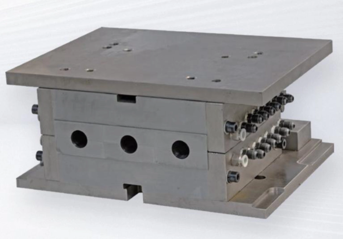
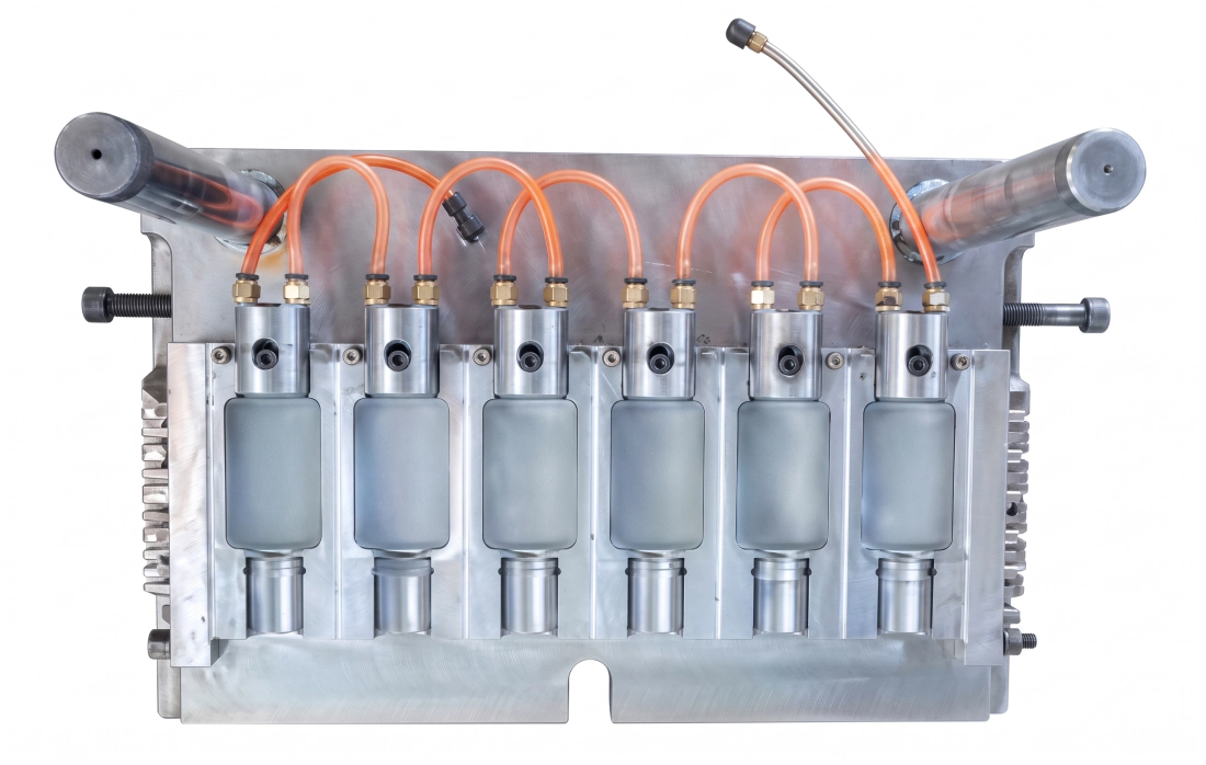
Sistema de canal caliente optimizado
El sistema de canal caliente para moldeo por inyección está diseñado para un flujo sin zonas muertas, lo que garantiza una mínima variación en el peso en gramos en todas las cavidades. La precisión del control de temperatura de ±1 grado evita la degradación de los materiales termosensibles y es esencial para una transparencia uniforme en los envases.
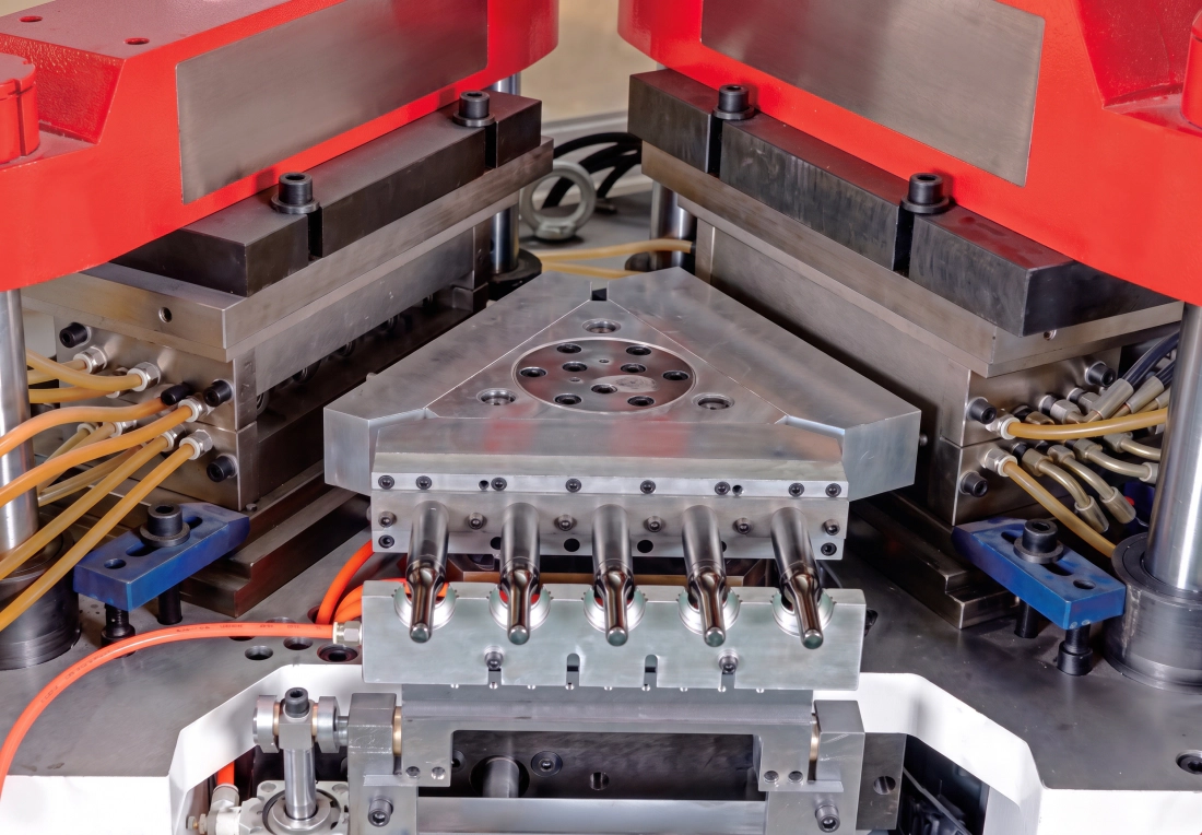
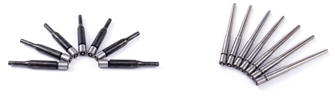
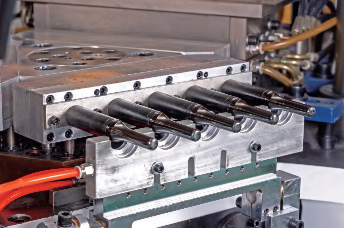
Diseño especial de varilla de núcleo
Los mandriles (varillas de núcleo) incorporan canales de refrigeración internos que reducen la temperatura del núcleo entre las estaciones de inyección y soplado, acelerando así la fase de enfriamiento. Los mandriles de ciclo rápido permiten que la EP40 alcance un ciclo en seco de 3,5 s sin sacrificar la uniformidad de la refrigeración de la preforma ni la estabilidad dimensional.
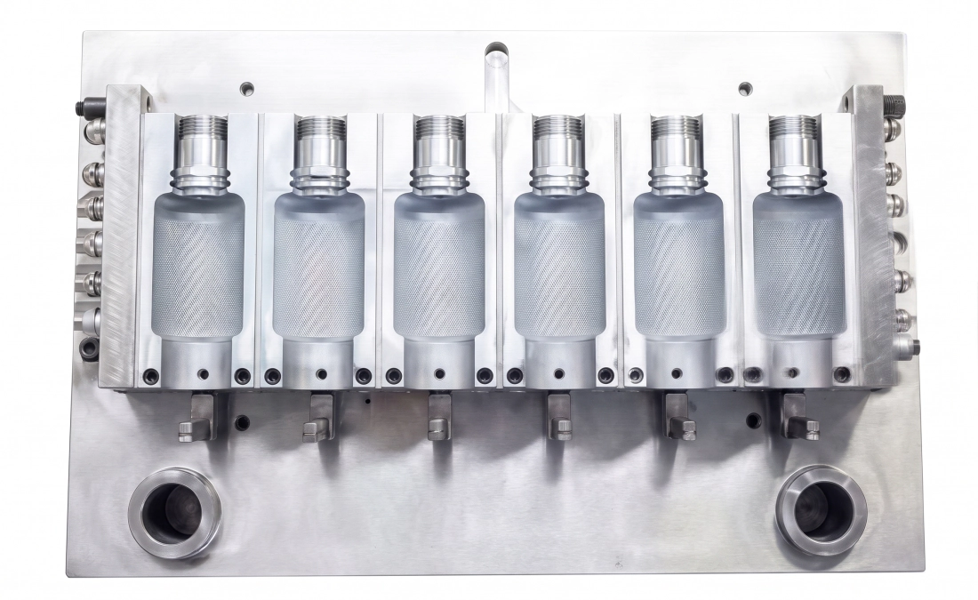
Moldeo por inyección-soplado frente a moldeo por extrusión-soplado: ¿Por qué IBM gana en el mercado de contenedores de precisión?
Los compradores que evalúan equipos para envases huecos suelen comparar IBM y EBM basándose únicamente en el costo de capital. La EP40 es más que una simple elección de máquina: es una elección de proceso que determina la rentabilidad de la producción a largo plazo y el nivel máximo de calidad que su planta puede alcanzar. La comparación que se muestra a continuación refleja diferencias de producción reales que afectan directamente el costo por cada mil botellas y su capacidad para obtener contratos de suministro para la industria farmacéutica y cosmética.
| No. | Elemento de comparación | Soplado por inyección (IBM) | Extrusión-soplado (EBM) |
|---|---|---|---|
| 1 | Consistencia del peso de la botella | Variación de peso aproximada 1% | Variación de peso aproximada 3% |
| 2 | Uniformidad del espesor de la pared | Espesor de pared uniforme en toda la superficie | El espesor de la pared varía de 10 a 201 TP3T. |
| 3 | Cuello de botella / Rosca | Sin destellos, sin raya en el cuello | Marca de corte, base y cuello debilitados. |
| 4 | Convexidad de la base | Fuerte convexidad positiva, base estable | Convexidad débil debido a la soldadura por presión |
| 5 | Residuos de materiales | Cero residuos: ni desperdicios ni desechos. | 20-40% de desecho de flasheo por presión |
| 6 | Capacidad de pared ultrafina | Menos adecuado para paredes muy delgadas | El espesor de la pared es ajustable mediante un controlador. |
| 7 | Sensibilidad ambiental | No es sensible a los cambios ambientales. | Se requiere ajuste frecuente |
| 8 | Recuento de cavidades y producción | Alta cavitación, alto rendimiento, boca plana | Menos cavidades, menor producción, cuello irregular |
| 9 | Vida útil y costo del moho | Larga vida útil del molde, ideal para producciones de alto volumen continuas. | Menor vida útil del molde, menor coste inicial. |
| 10 | Huella | Sistema integrado compacto, de tamaño reducido. | Más equipamiento auxiliar, mayor superficie. |
| 11 | Contenedor ovalado | Más difícil formar formas ovaladas | Más fácil formar perfiles ovalados |
Campos de aplicación y tipos de contenedores para el EP40
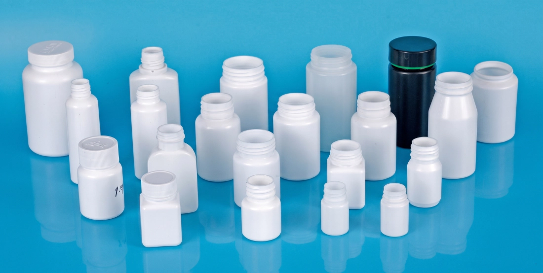
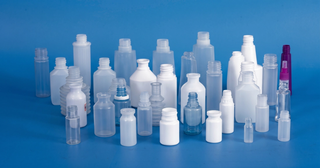
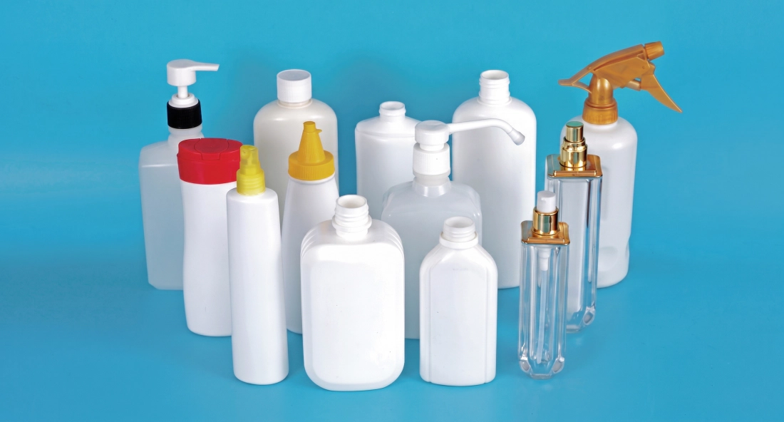
La EP40 está diseñada para producir botellas y envases desde 1 ml hasta el volumen máximo para este modelo, cubriendo toda la gama de necesidades de envasado primario en cuatro verticales de mercado principales. La tabla a continuación muestra los tipos de envases y segmentos de la industria donde esta equipo automático de moldeo por inyección-soplado ofrece su mayor rentabilidad comercial.
Industria farmacéutica
- Frascos para gotas oftálmicas (LDPE, 5-30 ml)
- Frascos para comprimidos y cápsulas orales (HDPE, 30-500 ml)
- Aerosol nasal y frascos con dosificador (PP)
- Frascos de medicamentos líquidos con tapones de seguridad para niños.
- Viales para vacunas y reactivos (LDPE, 1-20 ml)
- Frascos para pastillas de HDPE ámbar y blanco con certificación GMP
Industria cosmética
- Frascos aplicadores de desodorante roll-on (PE, 50-100 ml)
- Tubos y envases con aplicador de máscara de pestañas (PP, 5-20 ml)
- Frascos de esmalte de uñas (PS, 10-30 ml)
- Frascos con dosificador para lociones y sérums (PCTG, 30-200 ml)
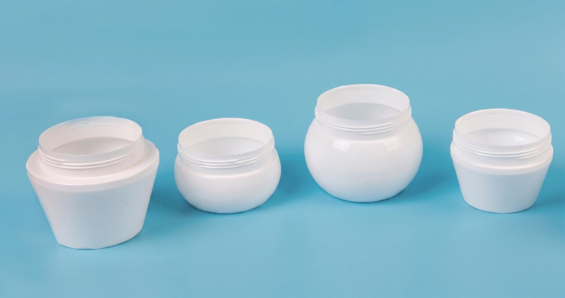
- Tarros de crema de boca ancha (PP/PS)
- Frascos de base de maquillaje y tónico
Productos y alimentos para bebés
- Biberones (PP, PPSU, 150-300 ml)
- Biberones dosificadores de fórmula infantil
- Envases para miel y jarabe (LDPE)
- Envases para bebidas especiales de pequeño volumen
- Botellas de muestra de aceite comestible
- Envases para yogur y productos lácteos
Productos químicos e industriales diarios
- Botellas de champú y acondicionador (HDPE/PP)
- Dispensadores de gel desinfectante y loción para manos
- Botellas de muestra de fluidos automotrices
- Botellas de concentrado de productos químicos agrícolas
- envases de productos de limpieza
- Frascos industriales para reactivos con cuellos precisos.
Sistema servohidráulico frente a sistema hidráulico convencional: un análisis técnico
La EP40 incorpora un sistema de accionamiento servohidráulico de alta respuesta que transforma radicalmente el consumo energético durante el ciclo de moldeo. En una bomba hidráulica convencional de desplazamiento fijo, el motor funciona a máxima velocidad independientemente de la demanda, desperdiciando energía en forma de calor durante las fases de baja carga, como el reposo, el enfriamiento y la eyección. El servomotor de la EP40 ajusta constantemente el desplazamiento de la bomba a la demanda real, reduciendo la velocidad del motor prácticamente a cero durante las fases de enfriamiento y reposo.
El resultado práctico: el consumo de energía operativa se sitúa en tan solo 52-701 TP3T de la potencia instalada total, en comparación con 80-901 TP3T para los sistemas convencionales. El aumento de la temperatura del aceite se reduce drásticamente (normalmente de 5 a 8 grados Celsius por hora, frente a 15-20 grados en los sistemas de bomba fija), lo que prolonga la vida útil de los sellos hidráulicos y reduce la frecuencia de los cambios de aceite y filtros. El ruido en la estación hidráulica desciende por debajo de 70 dB(A) durante las fases de refrigeración, mejorando el entorno de trabajo.
Durante la fase de inyección y sujeción a alta presión, el servomotor proporciona una respuesta instantánea de par máximo para un control preciso de la presión y la velocidad. Este control preciso reduce la formación de rebabas en la línea de separación y garantiza un peso constante de la preforma en cada inyección. En el sector farmacéutico y cosmético, donde cada miligramo de espesor de pared es crucial, esta repetibilidad se traduce directamente en menos rechazos y un menor coste de material por cada mil botellas.
Análisis de rentabilidad de la inversión y eficiencia de la producción: ¿Por qué elegir la EP40?
El costo de adquisición de la EP40 debe evaluarse en función de cinco factores de eficiencia cuantificables que determinan el costo por mil botellas y el período de recuperación de la inversión. Los ingenieros de compras que evalúan únicamente el precio de la máquina, sin considerar estos cinco factores, subestiman sistemáticamente la plataforma de IBM y sobreestiman la rentabilidad de la EBM para su aplicación específica.
1. Residuos de cero destellos
IBM no produce rebabas ni desperdicios en la línea de producción. EBM genera entre 20 y 401 toneladas de peso de botella como desperdicio por ciclo. Con 200 toneladas de PP al año, IBM, al no generar desperdicios, ahorra entre 40 y 80 toneladas de resina anualmente. A 1500 USD por tonelada, esto representa un ahorro de entre 60 000 y 120 000 USD en materia prima al año con una sola máquina.
2. Sin mano de obra para desbarbar
El proceso EBM requiere una operación de desbarbado secundaria, ya sea mecánica en línea o manual, lo que incrementa los costos laborales, el espacio que ocupa una segunda máquina y un punto adicional de fallo de calidad. Las botellas IBM de la EP40 salen de la cinta transportadora sin necesidad de ningún procesamiento posterior antes del llenado o etiquetado, lo que ahorra de 1 a 3 operarios por turno.
3. Rendimiento del ciclo de secado corto
La EP40 logra un ciclo de secado de 3,5 segundos. Con 6 cavidades de 60 ml, su producción anual, con 6000 horas de funcionamiento, supera los 37 millones de botellas. Esta concentración de producción en una sola máquina compacta reduce la inversión total en activos por unidad de capacidad en comparación con líneas de envasado electrónico de múltiples máquinas con una producción equivalente.
4. Cambio rápido de molde
El molde de inyección y el molde de soplado de la EP40 pueden cambiarse en 2-4 horas por un equipo de dos personas capacitadas. La recuperación de recetas desde el PLC elimina por completo el tiempo de preparación para trabajos repetitivos. Las instalaciones que procesan de 8 a 15 SKU en una sola EP40 logran una frecuencia de cambio de molde de 2 a 4 por semana con un tiempo total de inactividad por cambio inferior a 10% de las horas de producción disponibles.
Huella y eficiencia energética
La EP40, con unas dimensiones de 3,5 x 1,3 x 1,7 m, integra la inyección, el soplado y la eyección en una sola máquina. Compárese esto con una línea EBM de dos máquinas (extrusora, sopladora, prensa desbarbadora y cinta transportadora), que normalmente ocupa entre 3 y 4 veces más superficie para un rendimiento equivalente. Las conexiones de servicios (aire comprimido a 0,7-1,2 MPa, agua de refrigeración a 3,5 m³/h y conexión eléctrica de 20 kW) se realizan en un único punto, lo que reduce la complejidad de la instalación y los costes de mantenimiento.
El coste de construcción de una fábrica en un entorno de sala limpia de grado farmacéutico puede alcanzar entre 2000 y 5000 USD por metro cuadrado. El tamaño compacto del EP40 reduce directamente la superficie de sala limpia necesaria para producir un volumen determinado, un beneficio económico que no aparece en las tablas comparativas de maquinaria, pero que influye significativamente en la rentabilidad total del proyecto.
Características y estándares de diseño de moldes de la serie EP de IBM
- ■Diseño de cavidad activa y bloque de cuello Las cavidades del molde de inyección y los bloques del cuello son ajustables de forma independiente, lo que permite ajustar con precisión las dimensiones del cuerpo del tubo de la preforma sin necesidad de reemplazar todo el conjunto del molde. Los conductos de aceite y agua están diseñados específicamente para garantizar una distribución estable de la temperatura y facilitar el desmontaje.
- ■Grados de acero de primera calidad Los cuerpos de los moldes de inyección utilizan acero inoxidable 4Cr13 o acero aleado S136 de alta resistencia importado. El S136 es un acero pulido a espejo, resistente a la corrosión y con una dureza de hasta 52 HRC. Los cuerpos de los moldes de soplado pueden fabricarse en aleación de magnesio-aluminio para una conductividad térmica superior y una menor inercia en la torreta giratoria.
- ■Diseño optimizado de canal caliente y preforma El colector de canal caliente está diseñado para minimizar la desviación de peso en todas las cavidades y reducir la variación del espesor de pared en el cuerpo de la preforma. El diseño del mandril garantiza un suministro de aire uniforme para una expansión de soplado constante y un enfriamiento rápido.
- ■Dimensiones precisas de la rosca del cuello y del sello Los diámetros interior y exterior de la boca de la botella, el paso de rosca y la geometría de la brida se mecanizan según las tolerancias del plano. La tasa de sellado de la tapa es de 100% en todas las muestras de la serie de producción.
- ■Sin destellos en el cuello ni en la base. - La geometría del proceso IBM elimina las rebabas en la línea de separación en la boca de la botella y las rebabas de soldadura por presión en la base. Las botellas salen de la EP40 sin necesidad de recortarlas en ninguno de los extremos.
- ■Métricas de consistencia del producto - El tamaño, el peso, la posición de la línea de separación y el espesor de la pared son uniformes en todas las cavidades y en todos los lotes de producción, lo que permite a los clientes farmacéuticos validar la producción estadísticamente por lote sin los costes adicionales de la inspección 100%.
Guía de selección de equipos: ¿Es el EP40 el adecuado para sus necesidades de producción?
Para seleccionar el tonelaje adecuado de IBM, es necesario calcular la intersección de tres variables: peso de la preforma, número de cavidades requerido y producción objetivo por hora. Utilice este marco para confirmar si la EP40 tiene el tamaño adecuado para su aplicación o para comprender qué parámetros de producción puede soportar.
Paso 1: Calcular el peso de la preforma
Tome el peso objetivo de la botella en gramos (incluyendo el cuello, el cuerpo y la base). Añada 2-5% para margen de proceso. El peso de inyección EP40 de 190/260 g debe ser igual o superior a (peso objetivo de la preforma x número de cavidades). Por ejemplo: una preforma de 5 g con 8 cavidades requiere un peso de inyección de 40 g, lo cual está dentro de la capacidad de 190/260 g.
Paso 2: Calcular el número de cavidades necesarias
La producción objetivo (botellas/hora) dividida por (3600 segundos / tiempo de ciclo en segundos) da como resultado las cavidades necesarias. Con un ciclo de 3,5 s y una producción objetivo de 10 000 botellas por hora: 10 000 / (3600 / 3,5) = 10 cavidades como mínimo. Consulte la tabla de cavidades anterior para confirmar que la EP40 puede ofrecer esta capacidad con su volumen de botellas.
Paso 3: Verificar el ajuste de la platina del molde
La disposición del molde de inyección (huella de la matriz de cavidades) debe ajustarse al tamaño máximo de la platina EP40 de 480 x 340 mm. Las aplicaciones con botellas anchas (diámetro superior a 120 mm) o altas (altura superior a 220 mm) superan las dimensiones del molde EP40 y requieren un modelo de mayor tamaño. Confirme el diámetro exterior y la altura de su botella antes de especificar el número de cavidades.
Paso 4: Material y presión de inyección
El PP requiere mayor presión de inyección y temperatura de fusión que el LDPE. El PC y el PETG requieren temperaturas de cilindro aún más elevadas y un tiempo de plastificación más prolongado. La presión de 14 MPa del sistema hidráulico EP40 y su motor de 11 kW proporcionan las fuerzas de inyección necesarias para el PP y los materiales de grado técnico con el peso de inyección nominal. Confirme las especificaciones de su resina con el equipo de aplicaciones de EVER POWER antes de realizar el pedido.
Los ingenieros de aplicaciones de EVER POWER ofrecen asesoramiento técnico gratuito previo a la venta para validar las dimensiones, el material, el número de cavidades y el objetivo de producción de su envase según las especificaciones EP40. Contáctenos con el dibujo de su botella y el resumen de producción para obtener una confirmación por escrito de su idoneidad.
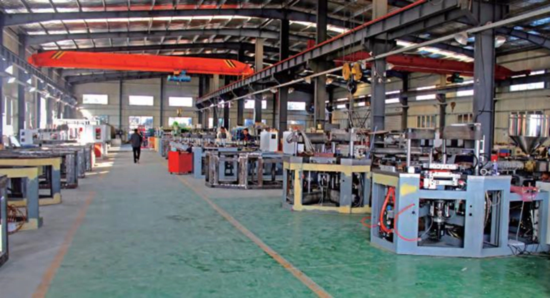
Descripción general de la estructura de la máquina y directrices de mantenimiento.
La EP40 se basa en tres módulos funcionales principales. Comprender sus requisitos de mantenimiento es fundamental para mantener los parámetros de rendimiento de la máquina (ciclo en seco, tasa de producción y calidad del producto) durante toda su vida útil.
Módulo 1 - Unidad de inyección: husillo, cilindro, canal caliente
La unidad de inyección funde y dosifica el plástico en la cavidad de la preforma. Mantenimiento diario: compruebe los perfiles de temperatura del cilindro con respecto a los puntos de ajuste, inspeccione la punta del husillo y el anillo de retención para detectar indicadores de desgaste y verifique que las temperaturas de la zona del canal caliente estén dentro de los 2 grados de los puntos de ajuste antes de la puesta en marcha. Semanalmente: inspeccione las bandas de aislamiento del cilindro, compruebe los sellos del cilindro de inyección para detectar fugas de aceite y purgue cualquier contaminación de color de la producción anterior. Mensualmente: extraiga y limpie el anillo de retención y el conjunto de la punta del husillo; inspeccione las aletas del husillo para detectar desgaste y mida el diámetro del orificio del cilindro para comprobar la holgura. Reemplace el cilindro si la holgura excede la tolerancia del fabricante para evitar el desbordamiento de la masa fundida y la inconsistencia en el peso de la inyección.
Procedimiento de purga: al cambiar de colores oscuros a claros o de resina de ingeniería a resina común, utilice un compuesto de purga comercial a una temperatura del barril 10 grados superior a la del nuevo material. Realice de 5 a 10 ciclos de purga antes de cambiar al nuevo material. Nunca deje el barril inactivo a la temperatura de procesamiento durante más de 20 minutos sin purgarlo; la degradación térmica durante los periodos de inactividad es la principal causa de la contaminación por motas negras al reiniciar el proceso.
Módulo 2 - Unidad de sujeción e indexación rotativa
El sistema de sujeción y el indexador rotatorio soportan las mayores cargas mecánicas y requieren una precisión de posicionamiento extrema. Diariamente: aplique grasa a las superficies de las barras de unión y a los rieles guía de la mesa giratoria según el programa de lubricación (EVER POWER especifica el grado de grasa; no la sustituya por grasa de uso general, ya que podría perder viscosidad a la temperatura de funcionamiento). Inspeccione el cilindro de sujeción hidráulico para detectar fugas de aceite en el sello del vástago. Preste atención a cualquier ruido inusual durante la rotación de indexación; cualquier clic metálico o vacilación indica que el cojinete del divisor angular requiere inspección.
Mensualmente: compruebe el paralelismo del plato con un comparador de cuadrante en cuatro posiciones de la barra de unión; una desviación superior a 0,05 mm requiere un nuevo ajuste. Compruebe la precisión de la posición de indexación colocando un comparador de cuadrante contra una superficie de referencia en la torreta y verificando que la misma posición se repita con una precisión de 0,02 mm después de 100 ciclos de indexación consecutivos. Si se observa alguna desviación, ajuste el tope mecánico o póngase en contacto con el servicio técnico de EVER POWER.
Módulo 3 - Sistema hidráulico y circuito de refrigeración
El sistema hidráulico es la columna vertebral energética del EP40. La presión del sistema está ajustada a 14 MPa. Diariamente: compruebe el nivel de aceite hidráulico en el visor del depósito, verifique la temperatura del aceite (rango de funcionamiento normal: 40-55 grados Celsius; por encima de 60 grados indica un problema en el circuito de refrigeración o una obstrucción en el filtro) e inspeccione todas las conexiones visibles de las mangueras hidráulicas para detectar fugas. El indicador del filtro de aceite debe revisarse cada 250 horas; un indicador rojo requiere el reemplazo inmediato del elemento filtrante, no se puede posponer.
Circuito de refrigeración: la EP40 requiere agua de refrigeración limpia y libre de incrustaciones a una presión de 0,3-0,4 MPa y un caudal de 3,5 m³/h. Instale un sistema de tratamiento de agua antes de la máquina para evitar la acumulación de incrustaciones de calcio en los canales de refrigeración del molde. Una acumulación de incrustaciones de tan solo 1 mm en un canal de 6 mm reduce la eficiencia de refrigeración en más de 30%, lo que prolonga los tiempos de ciclo y reduce la producción. Enjuague los circuitos de refrigeración anualmente con una solución desincrustante. El agua del enfriador debe tener un pH neutro (6,5-7,5) y contener un inhibidor de corrosión compatible con los materiales de moldes de aleación de cobre y aluminio.
Soluciones llave en mano y servicios de personalización de EVER POWER
EVER POWER suministra la EP40 como máquina independiente o como componente central de una línea de producción de botellas llave en mano. Para los clientes que están instalando una nueva planta o ampliando su línea de productos de envases, la solución llave en mano elimina el riesgo de integración que supone adquirir la máquina IBM, los moldes, los equipos auxiliares y los equipos posteriores de diferentes proveedores.
Diseño y fabricación de moldes
Los ingenieros de EVER POWER desarrollan conjuntos de moldes de inyección y soplado a partir de planos de botellas o archivos 3D del cliente. Moldes de canal caliente multicavidad en acero S136 o 4Cr13. Prototipos de moldes de una sola cavidad para la validación del envase antes de la producción de moldes de alta cavidad. Pruebas de moldes T0 realizadas en fábrica antes del envío.
Integración de equipos auxiliares
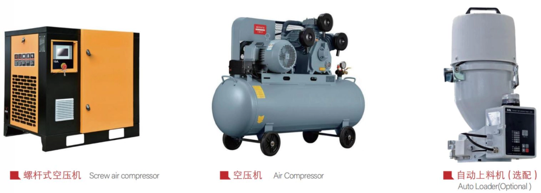
La línea llave en mano EVER POWER incluye: compresor de aire de tornillo, tanque y secador de aire, controlador de temperatura de molde, enfriador industrial, cargador automático, cinta transportadora, sistema de serigrafía y etiquetado, línea de lavado y secado, y máquinas automáticas de llenado y taponado. Todos los equipos auxiliares están especificados y preintegrados para adaptarse al caudal de producción EP40.
Sistemas de calidad posteriores
Máquina opcional de inspección visual en línea de botellas (sistema de visión artificial para la detección de fugas, deformaciones y contaminación), comprobador automático de fugas, máquina de embalaje automática y formadora de cajas. Para líneas farmacéuticas, el sistema de comprobación de fugas en línea y la inspección visual 100% están disponibles como módulos integrados compatibles con la velocidad de salida de la cinta transportadora EP40.
Configuración de salas limpias y GMP
Para clientes farmacéuticos que requieren producción con certificación GMP, EVER POWER ofrece personalización de máquinas que incluye: lubricación de sistema cerrado para evitar la contaminación de la zona de producto, carcasas de seguridad de acero inoxidable, carcasa de máquina con filtro HEPA para compatibilidad con salas blancas de clase 100 000 y asistencia en la documentación para los protocolos de cualificación de equipos (IQ/OQ/PQ).
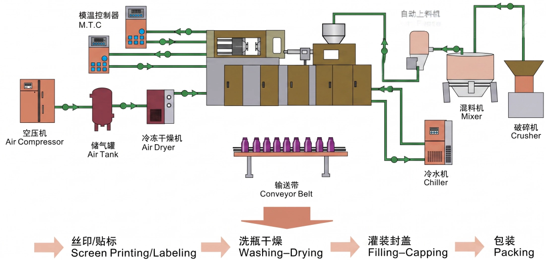
Equipamiento auxiliar disponible con el EP40
Control de calidad y normas de fabricación
Mecanizado CNC de componentes críticos
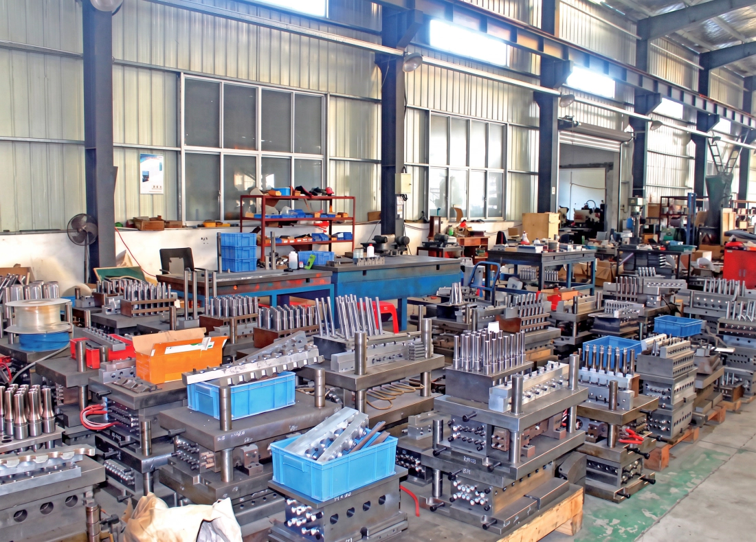
La bancada, las placas de sujeción y todas las superficies de precisión se mecanizan mediante CNC en una sola operación para garantizar la exactitud geométrica. El paralelismo de las placas se verifica mediante medición láser con una precisión de 0,02 mm. Los orificios de las barras de acoplamiento se rectifican con una tolerancia H7 para un ajuste perfecto de los rodamientos.
Endurecimiento por inducción de la barra de unión
Las barras de unión se someten a un endurecimiento por inducción de alta frecuencia hasta alcanzar una dureza superficial de 52-58 HRC, seguido de un rectificado de precisión. Este tratamiento superficial proporciona resistencia al desgaste frente al contacto deslizante repetido de las placas de sujeción durante millones de ciclos, sin que se produzcan rozaduras ni desgaste por fricción.
Limpieza del circuito hidráulico
Todos los circuitos hidráulicos se purgan, se someten a pruebas de presión y se verifica el recuento de partículas antes del montaje. La limpieza del aceite hidráulico se mantiene como mínimo en la clase 17/15/12 de la norma ISO 4406. La sensibilidad a la contaminación de las válvulas proporcionales y servoválvulas exige este nivel de limpieza para evitar el atascamiento del carrete de la válvula y la deriva del control.
Prueba de rodaje en fábrica de 72 horas
Antes de su envío, cada EP40 se somete a una prueba de funcionamiento continuo bajo carga de al menos 72 horas en fábrica. Durante este periodo, se miden muestras de la producción para verificar la consistencia del peso, la uniformidad del espesor de la pared y la precisión dimensional. Cualquier parámetro que no cumpla con las especificaciones activa una retención y una acción correctiva antes de que la máquina sea autorizada para su entrega.
Cumplimiento de la normativa de seguridad CE
La EP40 cuenta con la marca CE, en cumplimiento con los requisitos de la Directiva de Maquinaria de la UE. Entre sus características de seguridad se incluyen: puertas de seguridad con enclavamiento y circuito hidráulico de interrupción, protección fotoeléctrica en la zona de acceso del operario, parada de emergencia en todas las posiciones del operario y control manual del molde mediante dos manos. Se proporciona documentación CE con cada máquina.
Servicio posventa y soporte técnico
Instalación y puesta en marcha
Los ingenieros sénior de EVER POWER son responsables de la instalación, la puesta en marcha y las pruebas de aceptación. El ingeniero permanece en las instalaciones hasta que la máquina alcanza un estado de producción estable y todos los operarios reciben formación sobre su funcionamiento, el cambio de moldes y el mantenimiento rutinario. Los criterios de aceptación se acuerdan antes del envío y se documentan en el informe de puesta en marcha.
Programa de mantenimiento preventivo
EVER POWER ofrece un servicio de recordatorio de mantenimiento programado para todas las máquinas en funcionamiento. El calendario de mantenimiento abarca tareas diarias, semanales, mensuales y anuales. El mantenimiento proactivo previene averías imprevistas y reduce la necesidad de costosos envíos de repuestos de emergencia. Los clientes que siguen el programa de mantenimiento preventivo reportan consistentemente una disponibilidad de las máquinas superior a 95%.
Línea directa de servicio 24/7
La línea de atención al cliente de EVER POWER está disponible las 24 horas del día, los 7 días de la semana. Para averías urgentes en la producción, llame o envíe un mensaje a la línea de atención al cliente y un ingeniero cualificado le responderá en un plazo de 2 horas para diagnosticar el problema de forma remota. Si se requiere asistencia técnica presencial, EVER POWER enviará un técnico con el menor tiempo de respuesta posible para su ubicación.
Inventario de repuestos
EVER POWER mantiene un amplio inventario de repuestos para todos los componentes EP40, incluyendo sellos hidráulicos, cartuchos de válvulas proporcionales, bandas calefactoras, sensores de temperatura, correas de transmisión y componentes eléctricos. Los repuestos en stock se pueden enviar a nivel mundial en un plazo de 48 horas. Los artículos críticos de desgaste rápido están disponibles para el inventario local del cliente, según las recomendaciones de EVER POWER.
Programas de formación técnica
Además de la capacitación estándar para la instalación, EVER POWER ofrece módulos de capacitación especializados: operación de la máquina, optimización del proceso de moldeo, cambio y configuración de moldes, mantenimiento del sistema hidráulico y resolución de problemas de proceso para materiales específicos como PP, LDPE y PCTG. La capacitación puede realizarse en la fábrica de EVER POWER o en las instalaciones del cliente.
Preguntas frecuentes - EVER POWER EP40
¿Qué materiales puede procesar la EP40?
El EP40 es compatible con HDPE, LDPE, PP, PS (incluido el PS transparente apto para bacterias lácticas), ABS, EVA, material de maíz de origen biológico, PCTG y termoplásticos similares. Para resinas de ingeniería como PC, PETG y Tritan, la relación L/D del husillo de 22:1 y las 3+N zonas de calentamiento proporcionan el tiempo de residencia y el perfil de temperatura necesarios para una plastificación completa y sin degradación. Confirme el grado de su resina con el equipo de ingeniería de aplicaciones de EVER POWER antes de realizar el pedido.
¿Se puede utilizar el EP40 para la producción farmacéutica bajo normas GMP?
Sí. La EP40 se puede configurar para entornos de producción farmacéutica GMP. Entre sus características clave para el cumplimiento de las normas GMP se incluyen: el proceso de un solo paso elimina la transferencia de botellas entre máquinas, lo que reduce el riesgo de contaminación en sistemas de dos etapas; el sistema de lubricación cerrado evita la contaminación de la zona de producto con lubricante; y la máquina puede equiparse con una carcasa de seguridad de acero inoxidable apta para su instalación en salas blancas. EVER POWER proporciona la documentación del equipo para respaldar los procesos de cualificación IQ/OQ/PQ para la validación de instalaciones farmacéuticas.
¿Cuánto tiempo se tarda en cambiar el molde de la EP40?
Un equipo capacitado de dos personas puede completar un cambio completo de molde (molde de inyección, molde de soplado y ajuste del mandril) en la EP40 en aproximadamente 2 a 4 horas, dependiendo del diseño del molde y la frecuencia de cambio que tenga el equipo. La recuperación de recetas mediante PLC elimina el tiempo de reingreso de parámetros para los ajustes de molde repetidos. Las instalaciones que invierten en placas de sujeción de liberación rápida para la base del molde pueden reducir el tiempo de cambio a menos de 2 horas.
¿Qué certificaciones tiene el EP40?
La EP40 cuenta con la marca CE para el mercado europeo. Su diseño cumple con los requisitos de seguridad de la Directiva de Máquinas de la UE, incluyendo protecciones con enclavamiento, sistemas de parada de emergencia y normas de seguridad eléctrica. EVER POWER es un fabricante con certificación ISO. La documentación de la máquina se proporciona en inglés y, para mercados de exportación, puede facilitarse en otros idiomas bajo petición.
¿Cuál es el plazo de entrega para el EP40 y el juego de moldes asociado?
El plazo de entrega estándar para la máquina EP40 es de 45 a 75 días a partir de la confirmación del pedido y la recepción del depósito, dependiendo del programa de producción vigente. Los juegos de moldes se suministran normalmente en 60 a 90 días a partir de la confirmación final de los planos de la botella y las especificaciones del material. La máquina y los juegos de moldes pueden programarse para que lleguen simultáneamente y así facilitar una instalación coordinada. Para conocer el plazo de entrega actual, póngase en contacto con EVER POWER.
¿Listo para especificar el EVER POWER EP40 para su línea de producción?
Envíe el dibujo de su botella, el volumen deseado, las especificaciones del material y la producción requerida por hora a nuestro equipo de ingeniería de aplicaciones. Le confirmaremos por escrito el número correcto de cavidades y la configuración de la máquina, y le proporcionaremos una propuesta comercial detallada en un plazo de 3 días hábiles.
Información adicional
| editado | por hyw |
|---|
Productos relacionados
-
Máquina de moldeo por inyección-soplado EP60HE de alta velocidad, totalmente eléctrica, con ciclo de 2,5 s sin sistema hidráulico.
-
Máquina de moldeo por inyección-soplado de alta resistencia EP135 1350KN IBM de gran cavidad para botellas de cosméticos y productos farmacéuticos.
-

Máquina industrial de moldeo por inyección-soplado EP110 1100KN, equipo automático IBM para botellas de gran volumen.
-
Máquina de moldeo por inyección-soplado de alto rendimiento EP80 800KN Equipo de moldeo de botellas sin rebabas
-
Máquina automática de moldeo por inyección-soplado de un solo paso EP60 600KN para fabricantes de botellas farmacéuticas y cosméticas